Armbrain prototype #2: Bring it on!

on Saturday, November 1, 2014
Five months have passed from my last post about the Armbrain board. It's been a long and hard time for me. My awesome teammate who took care of signal processing and Matlab user interface left my team to pursuit her higher education abroad. Her contribution was huge. I took time to cover her role and study her code in the project. It's quite a challenge. 
I tried to turn these challenges to opportunities. I learned to use Matlab to acquire and process data. Along the way, I added some nice features to the signal acquisition function such as ring buffers and 8-channel plot. Some data structures concept in this book (Data Structures and Algorithms in C++) was implemented to reduce processing time in Matlab. The result was great! For the first time, I can plot 8+ channel from the ADS1299 chip with sampling rate at 250sample/second in realtime without dropping any package.

Now I got a solid signal acquisition, and visualization. Next step, I will test and debug the circuit signal, performance. Some initial measurement presented offsets and high noise. Let's see what will I got in the next update!  

Check out my video for this update:


MATLAB Arduino Tutorial 3, 4 and 5

on Saturday, August 16, 2014
Demo tutorial 3


Demo tutorial 4

Demo tutorial 5

MATLAB Arduino Tutorial 2.1 - Serial Connection between Arduino to MATLAB

on Tuesday, July 8, 2014
As I said in the previous tutorial, source code from Arduino Matlab team is not simple. They created wonderful tutorials as a guide for us to learn rather than step by step tutorials for maker. I spent time to study source code from MATLAB Arduino Tutorial 2 - Connecting and calibrating a 3-axis accelerometer .  It's not straight forward to understand their algorithm because the author explained it briefly. I broke it down to function by function, step by step to rewrite a new code base on theirs. I learned some useful techniques by doing this.

Here is my code for you to refer: Github repository
I went through my code in the video below. Enjoy.


Collecting EOG signal with ArmBrain [updated]

on Friday, June 6, 2014
As I said in my previous post, the next step after collecting ECG signal is EOG signal (eye movement signal to put it simple). It's in the milivolt range. It's good to know the EOG signal form before moving in to EEG signal because EEG signal will include EOG signal artifacts. On the other hands, my friend used EOG signals to control a wheel chair. She collected EOG signals by the Biosemi Active Two EUR 75,000 beast. My professor encouraged me to replace the Biosemi in that application with a low cost EEG/EOG recording device.

Setup
I haven't found a standard for EOG electrode placement as EEG. It's a large signal (1mV p-p from my measurement); it should be easy to collect anyway. I decided to follow the set up from 
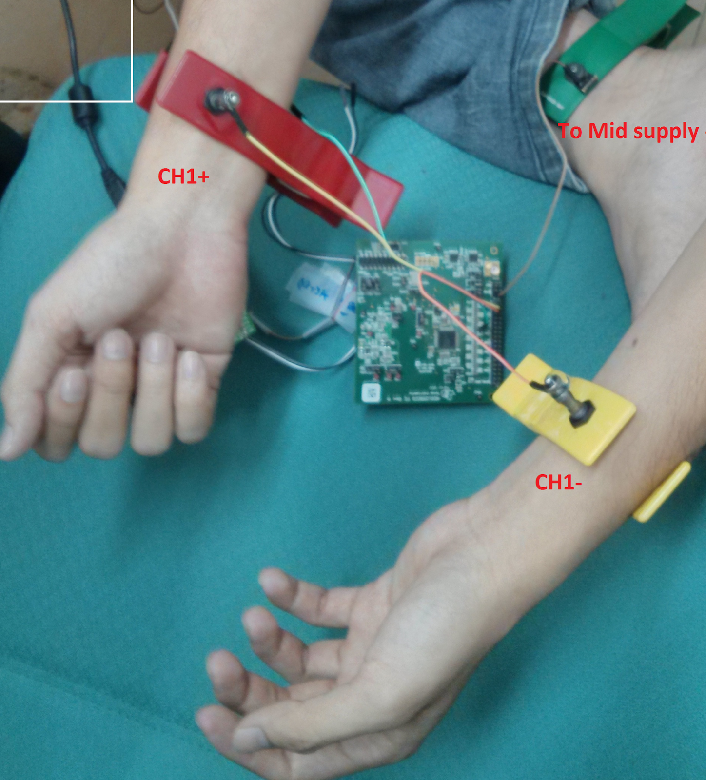
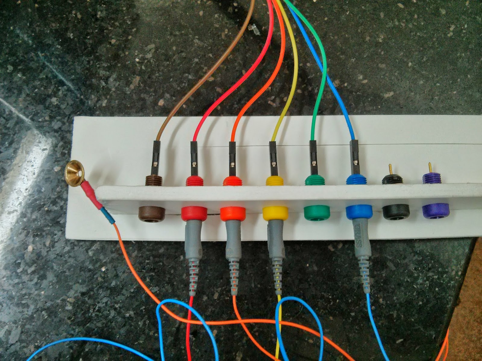
EEG hacker to compare results with Chip's trial.  Hardware and electrodes were the same as the last post. Below is the adapter from DIN 1.5mm touch-proof connector to regular breadboard jumper wire.


Gold cup EEG electrode adapter
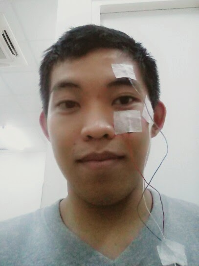
Gold cup EEG electrode secured by bandage. The reference electrode is on the right.


Result
I started with the eye blink artifact. I looked forward and blinked every 5s. The signal is very clear, strong and significant. We can use this signal for some simple computer interfaces such as playing a shooting game, sending a confirmation command of for a BCI application.
Eye blink test
Later I ran fft for the signal than I knew the trouble maker. It was the 50 Hz noise spike from the electricity system.

I applied a notch filter on top of the original high pass filter. The result is amazing! It's very sharp signal.


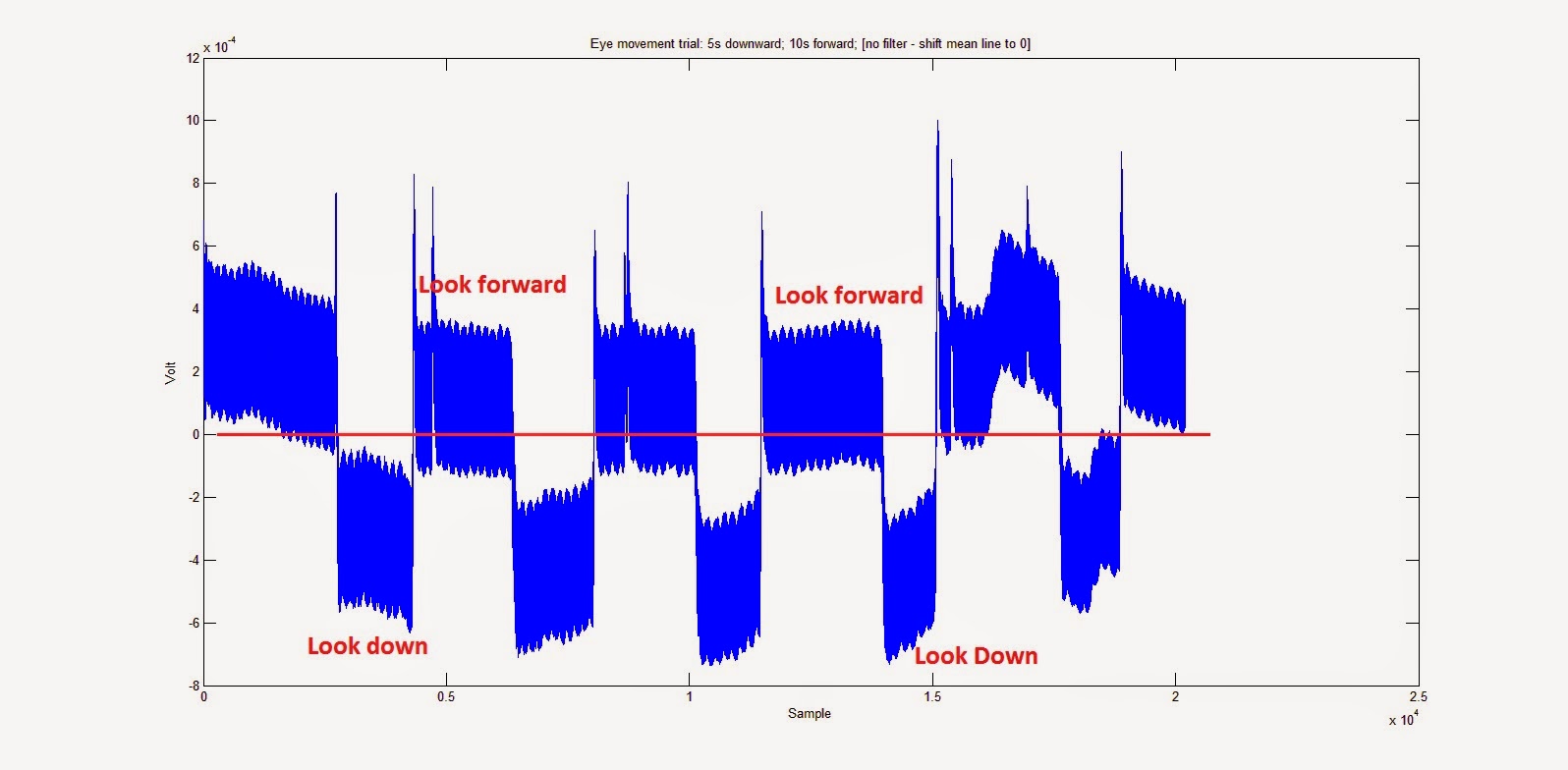
For the next trial, I looked forward for 10s and looked down for 5s. I designed two different intervals so I could easily differentiate two states. I may add another marking channel to ArmBrain board which takes a button input as a marker for a new state.

The result is sufficient for classifying the two states. The mean of forward state signal is higher than 0 baseline and the down state is well below the 0 baseline. I notice that the noise level for this trial is higher than the previous one. It's about 0.5mV p-p compares to 0.3mVp-p of the former data set. Also, I wonder if those spikes in the looking forward portion belongs to eye blink artifact. I may record videos for my trials to match with the result later.

Look Down Test

I retried again with a looking forward and up combination. I still got an acceptable graph. A distinct gap presents between the baseline of two states though the signal is not stable as last trial. The baseline drifted and, noise level increased.
Look up test

I call this a successful measuring session. I got satisfactory results. I have never known about EOG before. I want to thanks Chip from EEGhacker for his detail documentation. 

Next step: - try different setups to track eyeball movement like the sample below from BIOPAC.
- measuring EOG by EEG electrode location
- build a blink detection system for some fun applications


BIOPACK XY tracking


ECG signal from a simulator

on Thursday, June 5, 2014
Today I get the Phantom 320  ECG signal simulator from my lab. I will use it to test my hardware which called ArmBrain from now (Arm stands for the ARM micro controller; Later, if ArmBrain is used for BCI application, Arm also stands for users' hand).
ArmBrain Kit (TI daughter card is on the left; STM32F4 Discovery is on the right; The red board is the FTDI board)
ECG signal simulator
My setup: Left Arm(LA) and Right Arm(RA) signals from the simulator are connected to differential inputs of ADS1299 Channel 1. The Right Leg reference signal is connected to Bias electrode of the ADS board. Below are the graphs of data which I collected.

ECG signal from simulator collected by ArmBrain (3 wires set up)
I unplug the RL reference signal to test the output voltage graph without reference. It's noticeably noisier.

ECG signal from simulator collected by ArmBrain (2 wires set up - no reference)
The ECG signal simulator is a good tool to study and test bio-signal circuit.  I'm lucky to have it with me. If you don't have it, you can build one with Arduino kit. 


Collecting ECG signal with TI ADS1299 daughter card and STM32F4 Discovery

on Wednesday, May 28, 2014
I will blog about my journey from the beginning with the ADS1299 than I'll write about my ECG recording session. This project is my thesis so I can't post everything before I complete it. I started with the ADS1299 Evaluation module from January 2014. The module is helpful to get the feel of ADS1299 chip. A software comes with the module can collect couple seconds of data with different configurations. The designer of the Evaluation board created many jumpers and test points for multiple usage scenarios but it's very confusing to set them up. You will love it later when you understand the design.

Build my own module:
I decided to follow a tutorial from Chris Rorden's Neuropsychology Lab which shows a way to collect data from TI daughter card by any micro controller with SPI capability. The tutorial is on Arduino; I ported it to STM32F4 Discovery module.
ADS1299 EVM + STM32F4 Discovery + Bluetooth module

Collecting ECG signal:
My ECG set up for this time. another variation is at EEG hacker with disposable electrode.


My ECG data without right leg electrode
I expected to get a noisy signal without a right leg electrode. I don't think it's this bad. Probably I will redo the test later.
My ECG data with Right Leg Drive
It's very interesting that Chip from EEG Hacker can capture a good ECG signal with only two electrodes on two hands without a right leg or reference electrode. I can't get any useful data with only two electrodes. The noise overwrites my ECG signal.
I'm very happy with my ECG signal. It shows that my module is working at 1mV peak-to-peak signal. My next step is to test the EOG signal. EEG signal is still far away from now.

Update 1: My wiring configuration
Because Sebastian asked me to share the wiring configuration for the STMF4, I would like to share my note on the design. There are three main groups of pins in this design:
 SPI group: MOSI, MISO, CS, DRDY, START, SCK
UART group: TX, RX
Generic pins: Power, PWDN, Reset

STM32F4 Pin configuration with ADS 1299 EVM
Below are the pin details. Upper half presents signal pins. Lower half presents power pin.

Making EEG Electrode Adapter

on Thursday, May 22, 2014
My EEG recording prototype needs an electrode adapter to collect data from standard EEG electrodes. I followed tutorials from EEGhacker blog and Version2. Here is the result:

 From the Front

From the Top

Notes:
The tutorial is very clear and easy to follow. I purchased 10 different colors terminals from Plastic One . They match with my rainbow jumper wire and the EEG electrode:

Links for parts in Platics1.com doesn't work because they have just updated their website to a new template. I need to go to the site and search for a specific P/N. I got my parts for free as an educational support/evaluation parts. Thanks Plastics1!


AHRS/Head tracking test with GY-85

on Friday, May 16, 2014
I have been dreaming about using a Multiple Degrees of Freedom Sensor in my projects for a long time. It would be great for head tracking in BCI application for example. The 9 DOF sensor from ebay GY-85 has stayed on my desk for 6 months but I haven't got a chance to test it. After I got it running, I wrote this tutorial. Hope you will use it for your great projects.


The detail original tutorial is based on the Sparkfun  9DOF Razor IMU. Mine is a GY-85 and an Arduino Fio. You can port it to any other arduino with ease.
Physically different boards


Similar electrical units

As you can see from the picture above, two configurations are very similar. To get the GY-85 to work , you need to connect it to 5V(prefered) or 3.3V from the Fio is still OK. Then hook up the SCL, SDA as below:
GY-85
Vcc_in -> 5 volt
GND -> Ground/GND
SCL -> A5 
SDA -> A4


Now you can start to follow the original tutorial . When you reach the section: Uploading the firmware> Hardware option, please choose this option:
#define HW__VERSION_CODE 10724 // SparkFun "9DOF Sensor Stick" version "SEN-10724" (HMC5883L magnetometer)

Why? Because the stick is almost the same as the GY-85 ( without the Atmega on it) and the GY-85 comes with the HMC5883L. Push the code to arduino. Data should appear as mentioned in the tutorial. The rest of the tutorial is straight forward.

Do share with me your success stories. Good luck!

ps: another great head tracking project with similar configuration is here 

MATLAB Arduino Tutorial 2.0 - Serial Connection between Arduino to MATLAB ( Streaming value)

on Wednesday, May 14, 2014

In the previous post, I demonstrated how to exchange string value between Matlab and Arduino. It's very simple but effective to test the serial port communication. In this post, I will show you how to continuously stream value from analog read of arduino to Matlab plot.

Initially, I intend to post the source code for the MATLAB Arduino Tutorial 2 - Connecting and calibrating a 3-axis accelerometer but the code for this tutorial is so complex. The author blends many different MATLAB functions to the barebone of the code. I can't figure them out for now. I try to find another tutorial which tells a simple way to stream int value from arduino to MATLAB. It's in Spanish. Don't worry, it's easy to understand. The code is very clear.

Matlab+Arduino: Serial port communication [geekytheory.com]

In this video, the author graph the voltage of a potential meter measured by an analog pin of arduino, and graph it by Matlab continuously

Arduino code: read data from analog pin A3 every 100ms, send data to serialport. You can choose any pin.
 // the setup routine runs once when you press reset:
void setup() {
  // initialize serial communication at 9600 bits per second:
  Serial.begin(9600);
}
// the loop routine runs over and over again forever:
void loop() {
  // read the input on analog pin 0:
  int sensorValue = analogRead(A3);
  // print out the value you read:
  Serial.println(sensorValue);
  delay(100);        // delay in between reads for stability
}
Matlab code: I commented in English
function Matlab_Arduino(numero_muestras)
close all;
clc;
%% matrix to store output value
y = zeros(1,1000);


%%delete(instrfind({Port'},{'COM3'}));
%initiate COM Port
puerto_serial = serial ('COM3');
puerto_serial.BaudRate = 9600;
warning('off','MATLAB:serial:fscanf:unsuccessfulRead');

fopen(puerto_serial);

%counter of samples
contador_muestras=1;

%initiate figure property
figure('Name','Serial comm')
title('SERIAL COMMUNICATION MATLAB ARDUINO');
xlabel('number mustra');
ylabel('Voltage');
grid on;
hold on;

%plot received value until counter samples reach number of prefer samples
while contador_muestras <= numero_muestras
    ylim([0 1024]);
    xlim([contador_muestras-20 contador_muestras+5]);
    valor_poten = fscanf(puerto_serial, '%d')';
    y(contador_muestras) = (valor_poten(1));
    plot(contador_muestras, y (contador_muestras),'X-r');
    drawnow
    contador_muestras = contador_muestras+1;
end
%close port
    fclose(puerto_serial);
    delete(puerto_serial);
    clear all;
    
end


Good luck!

MATLAB Arduino Tutorial 1 - Serial Connection between Arduino to MATLAB to USB

The Matlab Arduino team created awesome tutorial on how to connect matlab with arduino through serial port. They provide these tutorials as a guidance for those who want to do similar things. Source code is not provided. I think it would be helpful to publish the code for those who want to try. I will also comment about some pitfall that I went through when I follow these videos.

My arduino code:
The original video doesn't show the arduino code in the loop portion. I put a digitalWrite for pin 13 as a confirmation for the successful connection, ie pin 13 will lit up after a serial connection is set up successfully between arduino and Matlab:

void setup() {
  // initialize serial communication at 9600 bits per second:
  Serial.begin(9600);
  pinMode(13, OUTPUT);
  Serial.println('a');
  char a = 'b';
  while (a != 'a')
  {
    a = Serial.read();
 
  }

}
// the loop routine runs over and over again forever:
void loop() {
  digitalWrite(13,HIGH);
}

Matlab code
I use the same code as the video. IMPORTANT: you must save this code as a setupSerial.m file in the same folder before executing the function:
function[s,flag] = setupSerial(comPort)
flag = 1;
s = serial(comPort);
set(s,'DataBits',8);
set(s,'StopBits',1);
set(s,'BaudRate', 9600);
set(s,'Parity', 'none');
fopen(s);
a = 'b';
while (a~='a')
        a = fread(s,1,'uchar');
end
if (a=='a')
    disp('serial read');
end
fprintf(s,'%c','a');
mbox = msgbox('Serial Comm setup.'); uiwait(mbox);
fscanf(s,'%u');
end


Getting started with STM32F4 Discovery and Keil C 5 Tutorial

on Friday, February 14, 2014
Here is a very good detail review about STM32F407 Discovery. It goes through all the capabilities of the STM32 family, components of the board, compiler consideration. I choose Keil as my compiler; I see many others use Coocox and GCC.

You should download and read the UM1472 - User manual - Discovery kit for STM32F407/417 lines. Read from the beginning, go through the Quick Start, Hardware Layout. It shows you how to test the board with pre-programmed code. Carefully read the ST-Link/V2 section, you will need it later. And don't forget to pay attention on some warning led, indication for overcurrent. Now you can plug the board to a USB port and follow through the Quick Start.

Next step, we will install STM32F407 Discovery Driver on a Win 7 machine. 
1. Download and install STM32 - ST Link Utility (STSW-LINK004).
2. Plug the board in the computer. If your computer recognizes the board, drivers were installed successfully. If not, go to step 3.
3. A wrong driver was installed. You need to remove it to give the way for the correct driver. Go to Computer>Manage devices> Remove the Pre-installed ST Link driver ( Google how to do it).
4. Unplug the boad > Then plug it in a gain > Done!

It's time to install the toolchain for Keil

1. Download and install Keil. The 4.7 version will have the STM32F4 Discovery Board example

2. If you install Keil 4.7 => Skip to Step 3. Keil 4.7 comes with pre-install STM devices and examples. If you install Keil 5, then install STMicroelectronics STM32F4 Series Device Support, Drivers and Examples  ( look for stm32f4 library with example pack)

3. Open windows explore, open the project at


4. Uncheck blinky folder property read only tick. Default property is read only to protect the file. Uncheck it for keil C to create axf file.


5. Open Keil, then open the example project (Blinky.uvproj) => Build all => Download
You should see 4 Leds are blinking at the same time.

Open:
You should check out this video tutorial on how to set up Discovery for Keil C. It used Keil 4.7; if you don't have 4.7, things may be very different as I experienced. To set up a Keil C project from stratch, you must read this application note. It's also a Keil C 101.

From Arduino to ARM Cortex M4 (STM32F407 Discovery)

on Wednesday, February 12, 2014
My EEG acquisition project needs more communication channels, processing muscle, speed than the Arduino can offer*. I decided to take this chance to explore the ARM Cortex M4 which is top of the line for MCU. I will never worry about the limitation of the microcontroller again. But, I started to worry about my knowledge to work with it.


In Arduino world, people speak the same language. We use the same IDE, quite similar libraries and boards. The assumption for most documentations, tutorials is that they are for beginners. It's easy to get started and do amazing things in hours! On the other hands, I learn do small projects with STM32 in couples of days or maybe...a week. People use many different IDE (Keil, IAR, Eclipse, Coocox...). Some guru write their own libraries; some use the STM standard peripheral library. Every generation of STM32 (F1,F3,F4). uses different standard libraries. You may find that the F1 library comes with more beginner examples (ex: simple SPI) while the F4 library comes with more complex examples (ex: DMA SPI). I recommend you take a look at F1 library although you work with F4 only because it comes with sample code.

 So far, I enjoy learning STM32F4 in a hard way. It's tough to navigate in its 1700+ reference manual. Once you got the hang of it, you will learn a lot about low level configuration and execution. It's the great thing compare to arduino. *Some other similar systems still use Arduino. For example: OpenBCI uses Arduino for there 8 channels system. They switch to a 16-bit system for the 16 channels version.